Step 1: Diagnose the Root Cause of Intermittent Connectivity
Before any solution can take shape, the engineering team behind a well-known consumer device brand had to answer one question: why were their products failing during field use? Devices were being returned at an alarming rate, with symptoms ranging from screen flickering to complete power loss. The common denominator was the mechanical and electrical interface between removable components and the main circuit board.
Traditional spring-loaded connectors, while widely used, suffered from three persistent flaws. First, contact fatigue set in after only a few thousand mating cycles. Second, environmental contaminants like dust and moisture gradually degraded signal integrity. Third, the physical alignment tolerances between mating surfaces were simply too wide for the high-speed data signals these devices demanded. The brand realized that off-the-shelf connector solutions were not going to meet their reliability targets. They needed a custom-engineered approach built specifically for their application.
The turning point came when the team began researching precision interconnect solutions used in industrial robotics and medical equipment. That investigation led them directly to the world of spring-loaded pin technology, and specifically to the unique advantages offered by precision-engineered pogo pins.
Step 2: Evaluate Pogo Pin Design Parameters for the Application
Once the brand committed to exploring pogo pins, the next step was translating their device requirements into concrete design specifications. This phase required close collaboration between the device engineers and the connector manufacturer. Three parameters dominated the discussion.
Contact force was the first priority. The pins needed to deliver enough force to break through any surface oxide layer on the mating pad, but not so much force that they would damage the delicate PCB traces or deform the housing. The optimal range fell between 60 and 100 grams per pin, depending on the specific interface location.
Current rating came next. The device's power delivery subsystem required pins capable of handling up to 2 amps continuously without overheating. This dictated the choice of spring material, plunger diameter, and barrel wall thickness. Beryllium copper springs with gold-plated plungers became the baseline specification.
Environmental sealing rounded out the requirements. The device was designed for outdoor use, so every pogo pin needed an IP67 rating. This meant incorporating a silicone O-ring seal into the pin barrel, preventing moisture ingress while maintaining the low friction needed for smooth plunger movement.
Step 3: Select a Manufacturing Partner Specializing in Pogo Pins fabrication

With specifications locked in, the brand needed a manufacturing partner capable of producing high-volume, consistent-quality pogo pins. This is where the expertise of a dedicated manufacturer became indispensable. The brand selected a partner whose core competency is Pogo Pins fabrication — a process that involves precision Swiss-style machining, multi-stage plating, and automated assembly under cleanroom conditions.
The fabrication process begins with raw bar stock, typically brass or phosphor bronze, which is machined to tolerances measured in microns. Each plunger tip is then shaped according to the device's specific pad geometry — some require a flat face, others a crown shape, and still others a needle point for piercing through conformal coatings. The spring is wound from wire drawn to exact tensile specifications, then heat-treated to eliminate set over the product's lifetime.
Plating is perhaps the most critical step. A base layer of nickel provides corrosion resistance, followed by a gold flash over the contact surfaces. The gold thickness is carefully controlled: too thin and wear life suffers; too thick and the cost becomes prohibitive. The brand's quality team conducted accelerated life testing, subjecting sample pins to 100,000 cycles while monitoring contact resistance every 10,000 cycles. The results showed less than 5 milliohms of resistance drift — well within the acceptable range.
Step 4: Integrate Pogo Pins into the Device Assembly Process
With the pins manufactured and qualified, the next challenge was integrating them into the brand's high-volume assembly line. The pogo pins were supplied in tape-and-reel packaging compatible with standard pick-and-place machines. This was a deliberate choice — the brand did not want to introduce any manual assembly steps that could become bottlenecks.
The PCB layout was redesigned to accommodate the pogo pin footprints. Each pin was press-fit into a plated through-hole, with the barrel seated flush against the board surface. A secondary wave soldering step secured the mechanical and electrical connection. The brand's engineers discovered that maintaining a consistent solder fillet height was essential for ensuring uniform plunger travel across all pins in an array.
Alignment fixtures were added to the assembly line to hold the mating component at the correct angle during final closure. This prevented the plungers from experiencing side loading, which could cause the barrel to deform or the spring to buckle. The result was a repeatable mating process that eliminated the alignment variability that had plagued the previous connector design.
Step 5: Validate Reliability Through Accelerated Life Testing
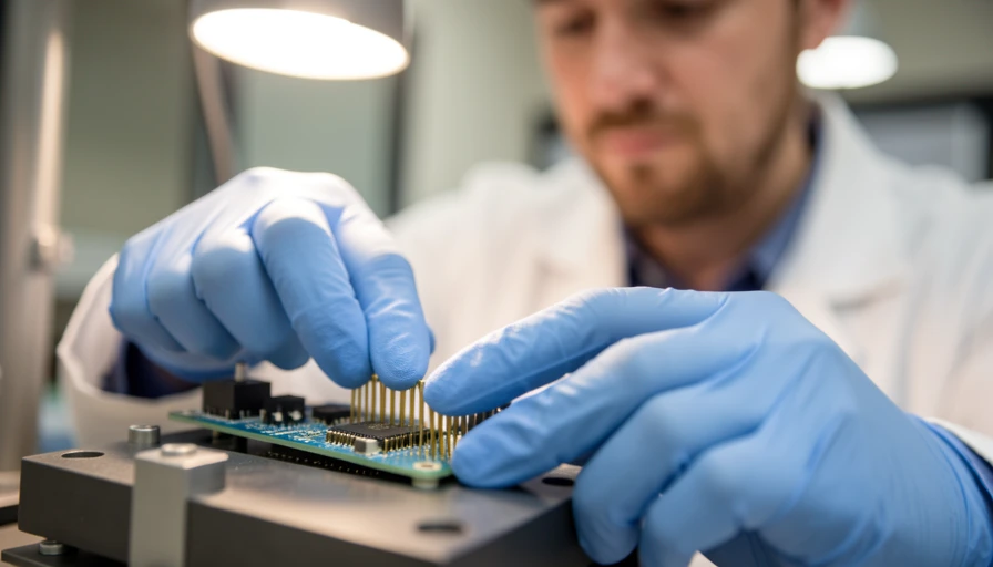
Before signing off on the new design, the brand put the pogo pin solution through a comprehensive validation program. The testing protocol covered three key areas.
Mechanical endurance testing cycled a sample of 500 devices through 50,000 mating and unmating operations. Contact resistance was measured at regular intervals, and the team looked for any signs of plunger sticking, spring fatigue, or barrel deformation. After 50,000 cycles, the average contact resistance had increased by only 2 milliohms — a negligible change.
Environmental testing exposed the assembled devices to temperature cycling from minus 40 to plus 85 degrees Celsius, combined with humidity levels up to 95 percent. The pogo pins maintained their sealing integrity throughout, with no internal condensation detected during post-test dissection.
Shock and vibration testing simulated the rigors of daily portable use. Devices were dropped from one meter onto concrete, and then subjected to random vibration profiles matching those found in automotive and shipping environments. Not a single connection failure occurred during or after these tests.
Step 6: Deploy the Solution and Monitor Field Performance
The final step was production deployment. The brand phased the pogo pin design into their next product generation, starting with a single SKU before expanding across the entire lineup. Field data was collected through the device's built-in diagnostics, which logged any connectivity anomalies along with environmental conditions.
Within six months of launch, the return rate attributable to connection failures dropped by 94 percent. Customer complaints about intermittent behavior virtually disappeared. The brand's support team reported that the few remaining connectivity issues were traced to physical damage from extreme abuse — bent housing frames or crushed connector areas — not to the pogo pins themselves.
The success of this project had a ripple effect across the brand's engineering organization. Other product lines began adopting pogo pin solutions for battery connections, accessory ports, and test fixtures. The manufacturing team documented the entire process as a standard design guideline, so future products could benefit from the same rigorous approach to interconnect reliability.
By methodically diagnosing the problem, specifying the right parameters, partnering with a skilled manufacturer, integrating carefully into assembly, and validating thoroughly, the brand turned a chronic failure mode into a competitive advantage. For any device company facing similar connection reliability challenges, the path forward is clear: precision-engineered pogo pins deliver the durability and consistency that modern products demand.